Interrupts and the Generic Interrupt Controller on AArch64
Introduction
I’ve been writing my own operating system (OS) from scratch for AArch64, called floss, and one of the first things I added support for was interrupts. I spend most of my time programming in “high level” languages (C/C++) and rarely have to consider interrupts and their existence at all. I enjoy peeling away at layers of abstraction and understanding how things work, so this is yet another technical deep-dive into something I find interesting.
We will go into detail of how interrupts work on AArch64, looking into the design of the Generic Interrupt Controller (GIC), and connecting the theory with practice by showing how I interface with interrupts in floss. Although this post is a bit long, it will not be exhaustive in any way. For that, you have the architecture specification. Instead, we’ll focus on key details and areas, noting ideas and concepts that were valuable to me in understanding the systems and procedures around interrupts.
If you’d rather skip to the “gist” of how to set up interrupts, see #Interrupt Handling and #Example.
Exceptions
Let’s take a step back and understand what an interrupt is and how it is classified in ARMv8, by taking a look at exceptions.
The CPU does not necessarily execute instructions aimlessly; it must be able to react to unanticipated events without wasting resources on polling. This is where exceptions come into play, allowing the CPU to detect and respond to events that require attention. An exception causes the CPU to temporarily suspend what it is doing and jump to code that handles it. Depending on the type of exception, execution may either be continued from where the exception occurred, or not.
The source of an exception is generally put in one of two classes: synchronous or asynchronous. A synchronous exception is something that is “invoked”, like a trap. An asynchronous exception is more or less unanticipated, and is triggered by, for example, external devices. An interrupt is defined as an asynchronous exception.
Types of Exceptions
There are four kinds of exception origins, each of which has its own handler. The first is a synchronous exception, and the other three are asynchronous exceptions.
- Synchronous/Debug (CPU exception occurred due to an instruction)
- Interrupt Request (IRQ)
- Fast Interrupt Request (FIQ)
- System Error (SError) (CPU exception unrelated to instructions, like a hardware failure)
Both IRQ and FIQ are asynchronous interrupts and occur due to events unrelated from the current stream of execution. The difference between IRQ and FIQ is that they’re classified separately with their own masks and exception paths. Rather than an FIQ being handled “faster”, it usually has higher priority and is handled in a different path. Whether an interrupt is sent as an IRQ or FIQ is generally determined by the GIC.
Exception Vectors
When an exception occurs, the CPU jumps to the corresponding entry in the table of exception vectors, shown below. An entry in the table is 128 bytes, which fits 32 instructions given that ARMv8 has a fixed instruction size of 4 bytes. So the full size of the table is 2048 bytes. 32 instructions is generally not enough for a meaningful handler, so instead, a trampoline is often inserted to jump to a handler located elsewhere.
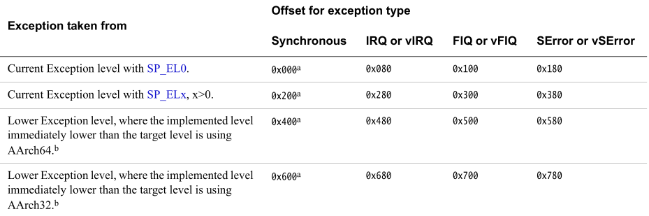
We’ll go into more detail on how to set up the exception vectors and handle interrupts in #Interrupt Handling.
Types of Interrupts
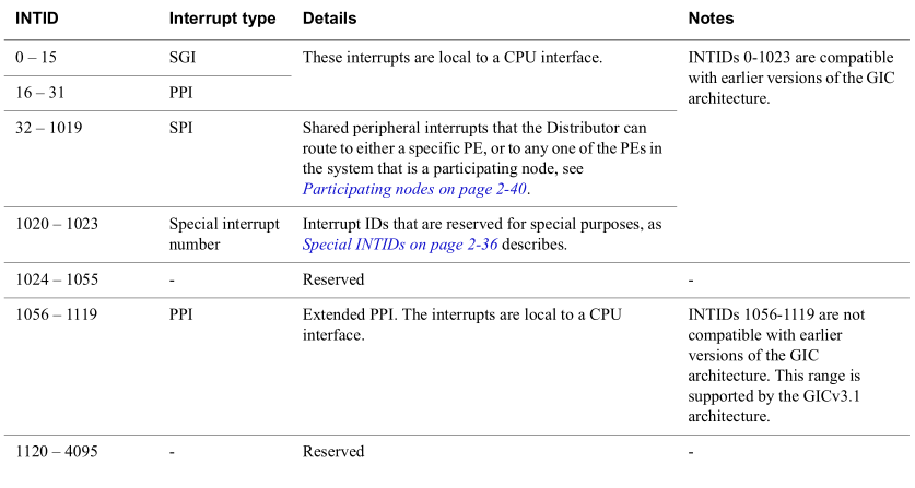
Interrupts, both IRQ and FIQ, are classified into one of four categories. Each category has a range of interrupt identifiers (INTIDs) that identify which category an interrupt belongs to. We won’t go into too much detail about Locality-specific Peripheral Interrupts (LPIs) in this post, but it is useful to know that the type exists.
- Software Generated Interrupt (SGI)
- Private Peripheral Interrupt (PPI)
- Shared Peripheral Interrupt (SPI)
- Locality-specific Peripheral Interrupt (LPI)
The table below maps INTIDs to interrupt types and provides additional details. INTIDs 4096–5119 are reserved for extended SPIs, while LPIs use INTIDs from 8192 up to an implementation-defined upper bound. A key takeaway is that interrupts local to a CPU interface (SGIs and PPIs) are represented by values 0–31.
Generic Interrupt Controller
The heart of interrupt management is the Generic Interrupt Controller (GIC). All interrupts flow through the GIC, which is made up of several interacting components. The GIC is part of the system on a chip (SoC) alongside the ARM CPUs, and is directly connected to the CPU cores via a CPU interface.
We are going to focus on the third version of the GIC (GICv3), which is generally supported by most ARMv8/ARMv9 chips (and QEMU!). Newer versions like GICv4 and GICv5 build on the same fundamentals as GICv3 but are not necessarily as broadly supported.
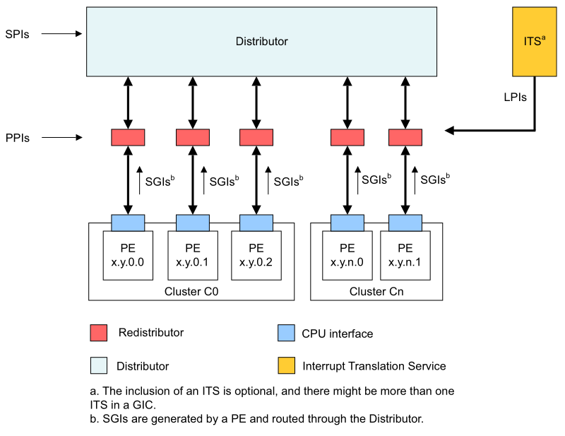
The main components of the GIC are: Distributor, Redistributors, and an optional Interrupt Translation Service (ITS). Together they make up the so-called Interrupt Routing Infrastructure (IRI), which interacts with processing elements (PE) via the Redistributors. Processing elements will be referred to as CPUs from here on.
Distributor and Redistributors
The Distributor is a shared entity, while the Redistributors belong to a specific CPU, so there is one Redistributor per CPU. The Distributor prioritizes and distributes interrupts that are not inherently private to a single CPU. These are primarily SPIs, which can be routed to any CPU. There are also SGIs, which are software-generated and can originate from any CPU and be routed to one or more CPUs. If an SGI is routed to a different CPU than the one generating it, it passes through the Distributor.
Redistributors handle interrupts that inherently belong to a specific CPU, which could have originated from the Distributor, or have been sent directly to the Redistributor. For example, a timer interrupt is a PPI that is sent directly to the Redistributor, since each core has its own timer hardware. Also, an SGI which is sent to the same CPU that generated it only passes through the CPU’s own Redistributor.
The Interrupt Translation Service (ITS) receives message-signaled interrupts and translates those messages into an LPI, and determines which CPU should receive the interrupt. One of the main producers of messages to the ITS is PCI/PCIe devices.
Interfacing with the Distributor and Redistributors
Interaction with the Distributor and Redistributors occurs via Memory Mapped Device Registers (MMDR), also referred to as Memory Mapped IO (MMIO). The base MMDR addresses for the Distributor and Redistributor can be temporarily hardcoded if you know the hardware layout (or where QEMU puts the addresses by default), but a more robust way is to parse them from the Device Tree.
I won’t go into too much detail about Device Trees and how they’re parsed here, but I’ve found the Device Tree specification immensely helpful when implementing my own parser.
From the interrupt controller entry in QEMU’s Device Tree (shown below), the address for the Distributor base (GICD) is 0x8000000, and the address for the Redistributor base (GICR) is 0x80a0000. As listed in the specification, not in the Device Tree, is that each Redistributor is on a 0x20000 stride offset from the Redistributor base.
intc@8000000 {
    reg = <0x00 0x8000000 0x00 0x10000 0x00 0x80a0000 0x00 0xf60000>;
    compatible = "arm,gic-v3";
    ...
}
From the base addresses for GICD and GICR, there is a long list of registers for both the Distributor and Redistributor(s). For example, at offset 0 from the GICD base register is the Distributor Control Register (GICD_CTLR). This register is used to enable interrupts in the Distributor. You can see a full list of registers in the GICv3 architecture specification.
Here’s a brief example of one approach to interface with the Distributor’s MMDRs in C++. It’s important that reads/writes are marked with volatile so that the compiler does not attempt to optimize them away.
static uintptr_t GICD_BASE = 0x8000000;

// Memory Mapped Device Registers for the Distributor
static const uintptr_t GICD_CTLR = 0x0000;
static const uintptr_t GICD_TYPER = 0x0004;
// ...

static volatile uint32_t* distributor(uintptr_t offset) {
  return reinterpret_cast<volatile uint32_t*>(GICD_BASE + offset);
}
Redistributors are a bit different by defining two 64KB frames, called RD (short for Redistributor) and SGI (Software Generated Interrupt). The RD frame is for controlling the overall behavior of the Redistributor along with how LPIs are generated in a system that does not include an ITS. The SGI frame is for controlling and generating PPIs and SGIs. Beware that some of the MMDRs are 32 bits and some are 64 bits.
static uintptr_t GICR_BASE = 0x80A0000;
static const uintptr_t GICR_STRIDE = 0x20000;
static const uintptr_t GICR_RD_OFFSET = 0;
static const uintptr_t GICR_SGI_OFFSET = 0x10000; // 64 KB

// Memory Mapped Device Registers for the Redistributors
static const uintptr_t GICR_RD_CTRL = 0x000;
static const uintptr_t GICR_SGI_IGROUPR0 = 0x080;
// ...

static volatile uint32_t* redistributor_rd(int n, uintptr_t offset) {
  return reinterpret_cast<volatile uint32_t*>(GICR_BASE + n * GICR_STRIDE + GICR_RD_OFFSET + offset);
}

static volatile uint32_t* redistributor_sgi(int n, uintptr_t offset) {
  return reinterpret_cast<volatile uint32_t*>(GICR_BASE + n * GICR_STRIDE + GICR_SGI_OFFSET + offset);
}
Interfacing with the CPU
Interaction with the CPU interface of the GIC happens via system registers that are specific to each CPU core, prefixed with ICC for Interrupt Controller CPU. Some ICC registers are, for example: ICC_PMR_EL1 for configuring the priority mask of the CPU interface, ICC_IAR0_EL1 for acknowledging interrupts, and ICC_IGRPEN0_EL1/ICC_IGRPEN1_EL1 for enabling interrupt groups.
Before any of the ICC registers can be accessed, the system register interface must be enabled via the ICC System Register Enable Register (ICC_SRE_EL1), by setting the first bit (position 0) to 1. Getting the hang of placing barriers, like isb or dsb, can be tricky, but here we need an isb to make sure that any instructions after the enable are guaranteed to observe the switch to enable the CPU interface. Without it, instructions that operate on ICC registers can observe that the system register interface is not enabled and fail.
mrs x0, ICC_SRE_EL1
orr x0, x0, #1
msr ICC_SRE_EL1, x0
isb
With the system register interface enabled, other ICC registers can now safely be configured as well.
Interrupt Configuration
Interrupt Group
To align interrupt handling with ARM’s exception model and security model, the GIC uses an interrupt grouping mechanism.
Any interrupt can be configured to be in either Group 0 or Group 1. In a system with two security states, Group 1 is subdivided further into a secure Group 1, and a non-secure Group 1. In such a system, Group 0 interrupts are expected to be handled at EL3, and Group 1 interrupts are expected to be handled in EL1 or EL2. In a system with only one security state, Group 0 interrupts are handled in the highest implemented EL, while Group 1 interrupts are expected to be handled in EL1 or EL2.
Groups are configured via the Distributor’s GICD_IGROUPR<n> MMDR or the Redistributor’s GICR_IGROUPR0 MMDR. The register(s) hold 32 bits, where each bit signals which group the corresponding INTID belongs to. For example, GICD_IGROUPR1 contains 32 separate bit values for INTIDs 32-63, while GICD_IGROUPR2 contains 32 separate bit values for INTIDs 64-95. Note that GICD_IGROUPR0 does in some cases alias to GICR_IGROUPR0.
On a system with one security state, a bit set to 0 means that the corresponding interrupt belongs to Group 0, a bit set to 1 indicates that it belongs to Group 1. This explains why only one register (IGROUPR0) is needed for the Redistributor, since PPI and SGI INTIDs are 0-31.
On a system with two security states, a bit set to 0 means that the corresponding interrupt is secure, and a bit set to 1 indicates that it is non-secure Group 1. To further specify which group the interrupt belongs to if the bit is set to 0, the GICD_IGRPMODR<n> and GICR_IGRPMODR0 for the Distributor and Redistributor respectively, are used. If the bit in the IGRPMODR<n> register is set to 0, the corresponding interrupt belongs to Group 0, and Group 1 if the bit is set to 1.
Which groups are enabled is configured via the Distributor Control Register (GICD_CTLR) MMDR. This register has different views depending on how many security states are enabled (one or two), and whether the access to the register is secure or non-secure. The code below is an example of how to interface with the GICD_CTLR register, where the Disable Security (DS) bit is checked to see whether the system has one or two security states enabled. In the code below, only Group 1 interrupts are enabled in both cases.
void GIC::v3::initialize_gic_distributor() {
  uint32_t ctlr = *distributor(GICD_CTLR);

  const bool ds = (ctlr & GICD_CTLR_DS) != 0;
  if (ds) {
    // If the DS bit is set to 1, then the system supports only a single
    // security state.
    ctlr |= (GICD_CTLR_E1NWF | GICD_CTLR_EnableGrp1);
  } else {
    // If the DS bit is set to 0, then the system supports two security states.
    // We know floss runs in non-secure, so use those toggles.
    ctlr |= (GICD_CTLR_E1NWF | GICD_CTLR_NS_EnableGrp1A);
  }

  *distributor(GICD_CTLR) = ctlr;

  // Ensure write to GICD_CTLR has completed before continuing
  while ((*distributor(GICD_CTLR) & GICD_CTLR_RWP) != 0) { }
}
Groups are then enabled on the CPU interface using the ICC Interrupt Group N Enable registers ICC_IGRPEN0_EL1/ICC_IGRPEN1_EL1, by setting the first bit to 1 to enable, 0 to disable. The code below enables Group 1 interrupts on the CPU that’s executing the instruction. Keep in mind that ICC instructions need to be executed on each CPU individually, so the msr ICC_IGRPEN1_EL1 below needs to be executed on each CPU that we want to enable Group 1 interrupts for.
mov x0, #1
msr ICC_IGRPEN1_EL1, x0
isb
Interrupt Priority
Priority is important in deciding which interrupt to take when several are pending. Interrupts, referenced by their interrupt ID (INTID), can be configured to have a priority between 0 (0x00) and 255 (0xFF), i.e., 8 bits. Additionally, the priority mask of each CPU can be configured, which is also a number between 0 and 255. It may be confusing at first, but a higher priority correlates with smaller numbers. Hence, the highest priority is 0, and the lowest priority is 255.
An interrupt is only forwarded to the CPU if its priority is higher (smaller number) than the priority mask of the CPU. If the priority of the interrupt is lower than the CPU’s priority mask, the interrupt is masked and will remain in a pending state until the CPU’s priority mask is lowered or the interrupt is re-prioritized.
The priority mask of the CPU is configured via the ICC Interrupt Priority Mask (ICC_PMR_EL1) system register. Like other ICC registers, ICC_PMR_EL1 is CPU-specific. The specification says that writes to ICC_PMR_EL1 are self-synchronizing, which means that an isb is not needed to make sure that subsequent instructions observe the new priority mask value.
mov x0, #255
msr ICC_PMR_EL1, x0
The priority of a specific INTID depends on whether it is associated with the Distributor (SPI) or a Redistributor (SGI, PPI). The Distributor and Redistributor work similarly in this context, both having their respective Interrupt Priority Registers in GICD_IPRIORITYR<n> and GICR_IPRIORITYR<n> MMDR. Each register contains four 8-bit values that define the priority for a corresponding interrupt. For example, GICD_IPRIORITYR0 contains four 8-bit values for INTIDs 0-3, while GICD_IPRIORITYR1 contains four 8-bit values for INTIDs 4-7.
void GIC::v3::set_interrupt_priority(int id, uint8_t priority) {
  if (id > 31) {
    // SPI
    volatile uint8_t* p = reinterpret_cast<volatile uint8_t*>(
        GICD_BASE + GICD_IPRIORITY_BASE + id);
    *p = priority;
  } else {
    // SGI/PPI: per-CPU, in the Redistributor's SGI frame
    for (uint32_t i = 0; i < NumRedistributors; i++) {
      volatile uint8_t* p = reinterpret_cast<volatile uint8_t*>(
          GICR_BASE +
          i * GICR_STRIDE +
          GICR_SGI_OFFSET +
          GICR_SGI_IPRIORITYR_BASE + id);
      *p = priority;
    }
  }

  asm volatile("dsb sy" ::: "memory");
}
Something that is easily missed in this context is that all 8 bits of each IPRIORITY<n> byte might not be implemented. This depends on which security state the CPU is running in, either Secure or Non-Secure. I won’t go into too much detail about the modes here. Depending on the state, it could be as few as 4 bits that are enabled, giving 16 different priority levels, up to the full 8 bits, with 256 priority levels. Refer to the specification if you care about high precision here.
Enabling/Disabling Interrupts
Interrupts must be enabled in either the Distributor (INTIDs >= 32), or the Redistributor (INTIDs 0-31) before they are able to be forwarded to CPU interfaces. Enabling interrupts is done via the Distributor’s GICD_ISENABLER<n> MMDRs or the Redistributor’s GICR_ISENABLER0 MMDR, and disabling interrupts is done via the Distributor’s GICD_ICENABLER<n> MMDR or the Redistributor’s GICR_ICENABLER0 MMDR.
The ISENABLER<n> and ICENABLER<n> registers work similarly to the IGROUPR<n> registers in that they are 32-bit registers, where each bit signals whether the corresponding interrupt is enabled or not. For example, GICD_ISENABLER1 contains 32 separate bit values for INTIDs 32-63, while GICD_ISENABLER2 contains 32 separate bit values for INTIDs 64-95. Note that GICD_ISENABLER0 does in some cases alias to GICR_ISENABLER0.
ISENABLER<n> is “write-1-to-set”, and ICENABLER<n> is “write-1-to-clear”, so there is no need to mask out other bits to preserve a previous value. Below is an example of how to enable interrupts via the ISENABLER<n> registers, and ICENABLER<n> works just the same way to disable interrupts.
const uint32_t id = ...
const uint32_t i = ...

// Distributor INTIDs
const uint32_t reg_index = id / 32;
const uint32_t reg_offset = reg_index * 4;
const uint32_t shift = id % 32;

*distributor(GICD_ISENABLER + reg_offset) = (1 << shift);

// Redistributor INTIDs. Only one register (ISENABLER0), so no extra calculation
*redistributor_sgi(i, GICR_SGI_ISENABLER0) = (1 << id);
Masking Exceptions
Some exceptions can be masked by setting bits in the DAIF system register, which instructs the CPU to not take the corresponding exception. If an exception is received while its type is masked, it remains in a pending state and will be taken when the exception is unmasked.
The DAIF system register has four bits that correspond to:
- D: When set to 1, debug exceptions are masked
- A: When set to 1, SError exceptions are masked
- I: When set to 1, IRQs are masked
- F: When set to 1, FIQs are masked
The debug bit only masks certain synchronous exceptions, like: watchpoints, breakpoints, and software step exceptions. Other synchronous exceptions like supervisor/hypervisor/secure monitor calls cannot be masked.
Since the DAIF bits begin at bit position 6 in the DAIF system register, a more accessible way is to use the DAIFSet and DAIFClr system register aliases. Additionally, masking/unmasking exceptions with DAIFSet and DAIFClr only affect the interrupt types that have their corresponding bit set to 1 in the immediate value. Interrupt types with their corresponding bit set to 0 in the immediate are unchanged.
msr DAIFSet, #0b0010 ; Mask IRQs
msr DAIFClr, #0b0010 ; Unmask IRQs

; Equivalent way to mask IRQs with the DAIF system register.
; Need to preserve other bits manually.
movz x0, #1, lsl #7
mrs x1, DAIF
orr x0, x0, x1
msr DAIF, x0
Interrupt Handling
Now that we’ve covered the major theory behind interrupts and how to configure them, let’s go over how to handle interrupts. Earlier we talked about the table of exception vectors, which is where the CPU jumps to when an interrupt request occurs. Let’s go into how to set up our own table of exception vectors and our own rudimentary interrupt handler for interrupt requests (IRQ).
The base of the exception vector table needs to be aligned to 2048 bytes (2 KiB), and as we noted in #Exception Vectors, each handler is 128 bytes, and needs to be aligned to 128 bytes. For brevity’s sake I’ve only included the handlers for the second exception origin. Entries marked vector . simply hang for now, by jumping back to itself continuously.
.macro vector label
.p2align 7 # align to 128 bytes
  b \label
.endm

.p2align 11 # align to 2 KiB
vector_table:
  # Order is:
  # 0: Synchronous/Debug (CPU exception occurred due to instruction)
  # 1: IRQ (Interrupt Request)
  # 2: FIQ (Fast Interrupt Request)
  # 3: SError (CPU exception unrelated to instructions)

  # ELn keep stack (SP_EL0 was used)
  # ...

  # ELn own stack (kernel mode, SP_ELx (x>0) was used)
  vector .
  vector irq_entry
  vector .
  vector .

  # 64-bit EL(n-1)->ELn
  # ...

  # 32-bit EL(n-1)->ELn
  # ...
A rudimentary interrupt handler is shown below. This handler does not save any register state before branching to the handler, which a real handler should do. Apart from this, there are three key steps in this handler that you should be aware of.
-
First, the CPU acknowledges the interrupt by reading the Interrupt Acknowledge Register for Group 1 (
ICC_IAR1_EL1). Note that you could also read Group 0 fromICC_IAR0_EL1, but we won’t cover that here. Reading this register both gives you the INTID of the received IRQ, as well as tells the CPU that this interrupt is “active”, which blocks the CPU interface from taking interrupts with lower priority. -
After branching to the interrupt handler and presumably handling the interrupt, write the INTID back to the End of Interrupt Register for Group 1 (
ICC_EOIR1_EL1). This moves the interrupt back to the inactive state, which signals the end of this interrupt. -
Finally, execute the
eretinstruction, which resumes execution at the place where the CPU was when the interrupt occurred.
irq_entry:
  mrs x0, ICC_IAR1_EL1

  # Branch to IRQ handler. Returns INTID in x0
  bl  irq_handler

  msr ICC_EOIR1_EL1, x0
  eret
The CPU knows where the table of exception vectors is located via the Vector Base Address Register (VBAR). User applications generally run in exception level 0 (EL0), which is not an exception handling level and has no corresponding VBAR entry, only EL1-3 can have entries. The code below shows how to set the VBAR for EL1. Note that updating the VBAR needs to be done before interrupts are enabled and able to be handled by the CPU. If not, the CPU might jump to bad code to handle the interrupt.
ldr x0, =vector_table
msr VBAR_EL1, x0
isb
Example
To tie all this together, let’s go over an example of the steps required to enable a specific interrupt. The interrupt we’re going to enable is the one associated with the Generic Timer, where the non-secure version has INTID 30. In a more robust setting you’d get the INTID from the Device Tree.
We are running our kernel in a non-secure EL1, which we’ll keep in mind when configuring the interrupt. Also, we won’t configure the Generic Timer here, and consider that it is already configured.
-
Enable Distributor
Unlike the Redistributors in the next step, the Distributor does not need to be woken up. Instead, we need to select which groups should be enabled (Group 0 or Group 1, modulo security states). We’re going to enable Group 1 here.
// Assuming the system only supports a single security state uint32_t ctlr = *distributor(GICD_CTLR); ctlr |= GICD_CTLR_EnableGrp1; *distributor(GICD_CTLR) = ctlr; -
Enable Redistributors
The Redistributor(s) are by default in a lower-power state to conserve energy. We need to wake the Redistributor by clearing the
ProcessorSleepbit in theGICR_WAKERregister. After updating the bit, we query theChildrenAsleepbit until it becomes 0, which indicates that the Redistributor has finished booting up. We need to do this operation for each Redistributor we want to wake up/enable.uint32_t current_redistributor = 0; uint32_t waker = *redistributor_rd(current_redistributor, GICR_RD_WAKER); waker &= ~GICR_WAKER_ProcessorSleep; *redistributor_rd(current_redistributor, GICR_RD_WAKER) = waker; // Ensure write to GICR_WAKER has completed before continuing asm volatile ("dsb sy" ::: "memory"); // Busy-wait until the ChildrenAsleep bit becomes 0, indicating that the // Redistributor has awoken while ( (*redistributor_rd(current_redistributor, GICR_RD_WAKER) & GICR_WAKER_ChildrenAsleep) != 0) { } -
Configure INTID 30
Let’s configure the specific INTID for the Generic Timer we’re interested in.
3.1. Set priority
We start by setting the priority of the interrupt. The specification says that the priority resets to an unknown value, so it is good practice to set the priority to a default value at the very least. For now let’s configure the priority to the maximum, 0.
uint32_t current_redistributor = 0;
volatile uint8_t* p = reinterpret_cast<volatile uint8_t*>(
  GICR_BASE +
  current_redistributor * GICR_STRIDE +
  GICR_SGI_OFFSET +
  GICR_SGI_IPRIORITYR_BASE +
  30 // INTID 30
);
*p = 0; // priority 0
3.2. Set group
Then let’s set the group of the interrupt to Group 1, which we enabled in the Distributor. Since the Redistributor handles INTIDs 0-31, we don’t have to calculate which
IGROUPR<n>to use, we just useIGROUPR0.uint32_t current_redistributor = 0; uint32_t igroupr0 = *redistributor_sgi(current_redistributor, GICR_SGI_IGROUPR0); igroupr0 |= 1 << 30; *redistributor_sgi(current_redistributor, GICR_SGI_IGROUPR0) = igroupr0;3.3. Enable interrupt
And finally enable the interrupt in the Redistributor. Since we’re using the
ISENABLER0register here which is write-1-to-set, we don’t have to read-modify-write the contents to preserve any other state.uint32_t current_redistributor = 0; *redistributor_sgi(current_redistributor, GICR_SGI_ISENABLER0) = (1 << 30); -
Enable PE/CPU-specific elements
Now we’ll cover the system registers associated with the CPU in configuring interrupts. Make sure you have set up the table of exception vectors before unmasking interrupts with
DAIFClr. See #Interrupt Handling.4.1. Enable CPU system registers
To use the CPU interface of the GIC we need to enable their use via the
ICC_SRE_EL1system register, by setting the first bit to 1.mrs x0, ICC_SRE_EL1 orr x0, x0, #1 msr ICC_SRE_EL1, x0 isb4.2. Set CPU priority mask
We need to configure which interrupt priorities the CPU interface will accept. For now we’ll set the priority mask to 255, which is the lowest possible priority, which makes all priorities (except 255) forwarded to the CPU.
mov x0, #255
msr ICC_PMR_EL1, x0
4.3. Enable CPU interrupts
Then we enable interrupts on the CPU interface, which means the CPU is able to receive interrupt requests. We do this by setting the first bit to 1, which is the only valid bit in the register.
mov x0, #1 msr ICC_IGRPEN1_EL1, x0 isb -
Unmask Interrupts
And to the final switch: unmasking interrupt requests on the CPU via the
DAIFClrsystem register, which is a shorthand to clear bits in theDAIFsystem register. Now the CPU is able to receive and handle interrupts!msr DAIFClr, #0b0010 ; Unmask IRQs
Conclusion
An interrupt is an asynchronous exception in AArch64 that is an unanticipated event that the CPU needs to handle. Interrupts are handled by the Generic Interrupt Controller (GIC), which has parts like the Distributor and Redistributors, along with interfaces to interact with each CPU core.
Configuration of the GIC (v3) is mainly done via Memory Mapped IO (MMIO), except for the CPU interface which is configured using system registers. We’ve gone over how to configure things like groups ({GICD, GICR}_IGROUPR<n>), priority ({GICD, GICR}_IPRIORITYR<n>), priority mask (ICC_PMR_EL1), enabling/disabling interrupts ({GICD, GICR}_{ISENABLER, ICENABLER}<n>), masking exceptions (DAIF), and how to set up a table of exception vectors where the CPU jumps to handle an exception. Lastly, we’ve tied all of this together in a step-by-step example of what configuration steps are necessary to enable and handle a specific interrupt, in this case INTID 30, representing the Generic Timer.
Even though this post is covering a lot, this is only the tip of the iceberg. My hope is that anyone else starting out writing their own OS or kernel can use this as a starting point, as a way to understand and build intuition of the necessary building blocks. I’ve spent too much time poring over the GICv3 architecture specification, and even though this blog covers the most important details, I recommend pondering the specification yourself.
As always, I hope you learned something new from reading this!